What you need to know to start a BITBUS project


BITBUS specification overview


Type: Master-slave network exchanging SDLC message frames. 248 bytes max. net data length per message.
Structure: Bus, terminated at both ends. Stubs and prolongation possible with the use of repeaters.
Media: Twisted pair cable (one pair, 120 Ohms characteristic impedance) with ground wire and screen. Second pair necessary only with passive repeaters - not with self-directing repeaters.
Electrical: Differential pair 0/5V as defined in RS485.
Protocol: SDLC bitsynchronous self-clocked NRZI with opening and closing flags, address checking and 16bit CRC check word.
Data rate: 62,5kBit/s, 375kBit/s or 1,5MBit/s.
Slaves: 28 per segment with repeaters after one segment, 250 maximum. More stations per segment with modern RS485-transceivers (ALS/LBC). Data rate with more than one repeater: 62,5kBit/s only
Extension: 300m per Segment at 375kBit/s, 1200m at 62,5kBit/s - higher rates with modern RS485 transceivers.
Connector: 9pin Sub-D-connector


There are 250 participants (nodes) allowed in a BITBUS network. Depending on hardware and manufacturer, the address needs to be set using jumpers, rotary switches or it might be programmed into EEPROM. Addresses 0 and 250..254 are reserved, 255 addresses the local network board processor from the master processor (source extension) and is used as broadcast address, a new IEEE1118 feature.

To keep things simple, there is only one master who originates all requests and gets replies from the slave nodes. A slave cannot transmit without being polled so there are no bus arbitration problems. As soon as the master has sent a request, it starts polling for an answer. Special very short messages are exchanged while waiting for a reply. More than one request can be sent to a slave before having a reply on the first one.

Unanswered requests are called outstanding messages. A typical slave can handle 8 outstanding messages.

Messages can be sent to 16 (8 on i8044) different tasks in a slave with task 0 being reserved for the RAC task (remote access and control interface), now named GBS (generic bus services) in IEEE1118. RAC and real-time-kernel are the layer 7 of BITBUS and support basic i/o functionality and remote user task control.

A BITBUS message basically is an SDLC message containing the BITBUS specific data as information field. SDLC is a bitsynchronous protocol defined by IBM and used very widely in all areas where data integrity is mandatory (HDLC, ISDN). The SDLC frame is handled in hardware by the serial line controller, i.e. address checking and CRC generation/detection need no processor overhead. In many implementations, the message is transferred into memory in the background (DMA) and the processor is interrupted if the transfer is complete.


Bitbus message structure:

While the outer SDLC frame is filled by system software, it is the user´s responsability to fill the BITBUS message (the double framed part in the drawing) with the following information:
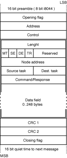
Length: Data field length + 7
Routing flags:
  • MT differentiates master requests (MT=0) from slave replies (MT=1).
  • SE (source extension) indicates that not the network processor is the originator of the message but a processor controlling it (for example the PC processor on a PC master board).
  • DE (destination extension) routes the message to a processor behind the receiving network node
  • TR is a transmit/receive flag. Used internally in the i8044 only. Set to "0".
Node address: specifies the destination (slave) 1..249
Source / destination task: 4 bits each specify the task number (0..15) of the source application (i.e. visualization app. or BITBUS-monitor or ... on the master PC) and the task number at the destination (0 for RAC, other for different user tasks).
Command / response byte: tells the slave what to do. For RAC/GBS the commands are predefined, user task commands are application specific. Contains error code on reply: 0 = no error, 80..9F are RAC error codes, others are user error codes.

The data field has a variable length from 0 to 248 bytes (0..13 on i8044). Usually the length of the expected reply is sent with the request to ease buffer management in the slave. For some RAC commands (i.e. Read I/O) there is a sequence of address/dummy bytes where the dummy bytes are filled with the data read on the given i/o address in the slave.

The CRC16 bytes and the ending flag are not part of the BITBUS message but are added by the SDLC-controller hardware.

For all standard applications, the user does not need to know more about the BITBUS internals. It is his duty to fill a buffer with the message information and to hand the buffer over to BAPI ( the BITBUS Application Programmers Interface) or the respective proprietary operating system function.

BITBUS Layer 7: RAC/GBS

One of the many advantages of BITBUS is it's definition of a standard command set called RAC "Remote Access and Control interface". With the extension of the commands under IEEE1118, they have been renamed to GBS "Generic Bus Services".

These commands can be used on BITBUS slaves of all vendors. RAC/GBS is addressed as task 0 on a slave and the desired command is selected in the command byte.

I/O access structure

For the example of an i/o-command, the BITBUS message buffer has to be filled with length, routing flags, node address, S/D task numbers and the RAC command number followed by a sequence of port addresses and data bytes: Add1, Data1, Add2, Data2,..

When it returns, the command byte is filled with an error code and the data bytes contain updated port data.

Memory access structure

In the case of memory commands the begin of the buffer structure is like with the i/o access structure, however the data field starts with an address pointer (high byte, then low byte) followed by the memory data to be written or dummy bytes with read commands. The length field is memory data bytes plus 9 (standard 7 + 2).

IEEE1118 address extension: To allow for memories greater than 64K (essential for processors like TLCS900 or MC68xxx with a large linear address space), address pointers can be extended as follows: Use BFH as command byte, then put into the first two bytes of the data field the address extension the upper 16 bits of a 32bit address. The third byte of the data field gets the command byte followed by the LSW of the memory address (for memory com-mands). Address extension also works on i/o-commands, as these are based on a 256 byte i/o address space, the extension is the upper 16 bits of a 24 - bit address, however.

Function IDs

To allow for tasks to be independent of a certain task number they are assigned by the system, function IDs are supported. In the task header (for iDCX51 and mCAT tasks) there's an entry for a function ID. The RAC/GBS-function GBS_GET_FUNC returns a list of 8 or 16 bytes with function IDs (sometimes even 32 as the 'DE'-bit is used by some manufacturers to extend the possible number of tasks). The first byte is the ID of task 0 (usually it contains 01, as this is the ID of the RAC/GBS-task), the second that of task 1 and so on. If FF is returned, there's a task with no function IDs, while a '0' means there is no task. BITBUS/IEEE1118 allows codes 80 to FE for user function IDs.

Using slave tasks

Most BITBUS slaves are equipped with a real time multitasking kernel where messages can be sent from the master to specified slave tasks.
These tasks are addressed exactly like the RAC/GBS task except that the destination task number isn't 0 but the number of the desired user task (which can be found out from the master using the mechanism described above.

In the table below, the function type specifies the structure of the data field with I for the I/ O-type structure and M for memory accesses as described above. C are control commands that have their specific data explained in the command description.


RAC/GBS commands

Command
Code
Command
Type
Command description
00 C GBS_RESET
Resets the slave. (Only function with no reply)
01 M GBS_CREATE
Creates and starts a task. Data field contains a pointer to the task header, MSB first. (16 bit + BF extension)
02 C GBS_DELETE
Deletes a Task. Data: task number as only data byte.
03 C GBS_GET_FUNC
Get function ID (see "Function IDs")
04 C GBS_PROTECT
Disables remote access commands
Data: 0= no protection, 1= protect memory, 2= write protect.
05 I GBS_READ_IO
Reads from port addresses.
06 I GBS_WRITE_IO
Writes to port addresses.
07 I GBS_UPDATE_IO
Writes and re-reads the port addresses specified.
08 M GBS_UP_DATA
Uploads a random memory block from the slave.
09 M GBS_DOWN_DATA
Downloads a memory block
0A I GBS_OR_IO
Logically ORs data in i/o ports with the mask given as data bytes. Re-reads the port. Used to set some bits.
0B I GBS_AND_IO
Logical AND used to reset bits.
0C I GBS_XOR_IO
Logical XOR used to toggle bits.
0D I GBS_WRITE_IRAM
Writes to internal RAM (hardware specific memory block). In the case of mCAT, these commands cover a predefined memory block.
0E I GBS_READ_IRAM
Reads from internal memory.
0F C GBS_GET_INFO
Returns hardware and task information (see below)
11 M GBS_UP_CODE
Uploads code from the slaves memory. Same as UP_DATA with processors that do not distinguish between code and data spaces.
12 M GBS_DOWN_CODE
Downloads code to slaves using special EEPROM/Flash-Eprom memory write procedure
15 C GBS_GET_TIME
Returns data structure (see GbsTime) with date and time info.
16 C GBS_SET_TIME
Sets time (see bitbus.h)
17 C GBS_SUSPEND_TASK
Suspends the task with the number given as only data byte.
1A C GBS_GET_TASK_ID
Returns task id for function id entered (similar to GBS_GET_FUNC but for one id only).
21 M GBS_FLASH_GET_ID
Returns 32bit Flash-EPROM type code in ext. addressing message.
BF M GBS_EXTEND_ADDR
Address pointer extension. See memory structure text for details.

RAC/GBS error codes

00 GBS_ERR_OK
No error
80 GBS_ERR_NO_DEST_TASK
Task does not exist
81 GBS_ERR_TASK_OV
No space for more tasks
82 GBS_ERR_REGISTER_OV
No register bank available
83 GBS_ERR_DUPLICATE_TID
New task has function ID that already has been assigned.
84 GBS_ERR_NO_BUFFERS
Buffer pool exhausted
86 GBS_ERR_BAD_TASK_DESC
Task descriptor (ITD) is not valid
87 GBS_ERR_NO_MEMORY
No more memory available
90 GBS_ERR_TIME_OUT
IEEE1118 Node not available
91 GBS_ERR_PROTOCOL
Unspecified error
93 GBS_ERR_NO_DEST_DEVICE
No extension available (see "Routing flags" )
95 GBS_ERR_PROTECTED
RAC/GBS command protected (see command 04)
96 GBS_ERR_NO_GBS
Unknown RAC/GBS command
97 GBS_ERR_BAD_COMMAND_LEN
Command length does not match command specification.


GBS Time Services

typedef struct {
BYTE zone, /* TIME ZONE : 0 = GMT, 8 = PST */
offset,

/* TIME OFFSET : 0..59 MINUTES */

day_of_week,

/* 1..7, MONDAY = 1. */

year,

/* 1980 = 0, 2235 = 255. */

month, /* 1..12, JANUARY = 1. */
day, /* 1..31. */
hour, /* 0..23. */
min, /* 0..59. */
sec; /* 0..59. */

} GbsTime;


System Info Structure

Data bytes Contents
0..5 6 character ASCII node name ("i8044","mCAT")
6, 7 ASCII version number ("3.1")
8 i8044 memory info or baudrate
9 BITBUS message length supported by this node
13..n Manufacturer specific data

Bitbus Installation

Although BITBUS has proved to be rather tolerant about cabling, RS485 definitions require some precautions that should be obeyed for optimum performance:

Cable

RS485 uses a balanced differential signal pair where one wire (usually named Data+) is on 5V (nominal) to signal TRUE data while the inverted wire (Data -) is on 0V and vice versa for FALSE data. The advantage of using a differential line is that a spike induced to the line ideally shifts both wires with the same voltage amount resulting in no change in the voltage difference between the two wires.

For good operation the two wires have to be twisted. The cable is available as so called "twisted pair cable". The voltages are allowed to float for a certain amount (-7 to +12V) against ground. Nevertheless there should be a possibility to reference against ground which calls for a third wire SIGNAL GROUND. There are many RS485 installations that just use the twisted pair but nobody would guarantee a groundless cabling. Usually a cable with two twisted pairs is used with on pair used for ground. A third pair is necessary in BITBUS nets using repeaters for the slave segments (the segments on the slave side of the repeater). This pair (RTS+/RTS- ) drives the amplifier signal direction input to switch from the standard (out to all slaves) to input if a slave in the segment wants to transmit

Termination

RS485 calls for termination of the signal lines at the extreme ends of the cable. A 120Ohm resistor between the wires of each pair gives the proper termination for the RS485 drivers. The cable should match this value as good as possible, i.e. have a characteristic impedance of 120Ohm or more. DB9 connectors with termination resistors are available from most manufacturers.

An even better way to terminate is to connect separate resistors from the supply voltage to the RS485 lines like described in the BITBUS book to take the lines to a defined idle state. This, however, can only be done inside the board where supply voltage is available. Thus many manufacturers supply switchable termination on their boards.

Shielding and earthing

Although shielding is not required by the BITBUS specification, all industrial applications should use a shielded cable. The cable screen should be connected to earth (foreign ground) on one side of the cable only (to prevent ground currents flowing through the BITBUS cable).

The resulting recommended cable is a 3 pair 0,25mm² twisted pair stranded wire with overall screen. It is called LiYCY(B) 3x2x0,25mm² in Germany.

Repeater operation

A standard RS485 driver like the 75176 drives 31 receivers on the twisted pair (there are advanced designs like the 75LBC176 that drive more than 50 receivers). BITBUS conservatively specifies 28 slaves. They all have to be within the cable length specified for the given bus speed (300m for 375kBit/s and 1200m for 62,5kBit/s, also specified well on the safe side). There are no stubs allowed for a node (i.e. it must be connected immediately to the bus line and not with a long cable to the bus. To allow for stubs or more slave devices (BITBUS logically addresses 250 nodes), repeaters can be used. A repeater is an amplifier, usually using a standard RS485 receiver and transmitter. It is part of the network just as any other BITBUS node (usually with electrically parallel input and output connectors) and has a third connector on the amplified side (which is the far side as seen from the master), the so called slave side.

As an amplifier cannot drive both data directions at the same time (BITBUS is halfduplex, i.e. uses the same wire pair to transmit to the slave and to receive from the slave), the transmit enable signal of the slave (RTS) is used to invert the amplifier direction that usually is outward only (master to all slaves). This signal is necessary only in the slave segments as the master doesn't need to know about it, just the repeaters on the way to the master.

BITBUS allows two repeaters in line between the master and any slave (but up to 28 with their master side in one segment) at 375kBit/s. Repeaters can thus be used to establish many stub lines.

Accessing a BITBUS slave

A BITBUS network is made up of many slaves that are controlled by a single master. To start with BITBUS, it might be the easiest way to use a master based on a PC. This requires a board (ISA, PC/104, PCI) to be plugged into the PC but it also requires some driver software. Most manufacturers provide a BAPI driver with their board, which is the BITBUS Application Programmers Interface introduced in 1999 as a BEUG standard.

BAPI opens the possibility to access different manufacturers boards or different boards of one manufacturer using the same master software. BAPI can be accessed by several PC applications (like a control program, a visualization, a debugger) concurrently and usually can address more than one BITBUS-board at a time.

Working with BAPI requires working knowledge of how to access a DLL from a controlling application on the PC. Apart from that, usage starts straightforward with a call to open one of the master boards (BitbusOpenMaster). A message to a slave is then assembled in a local structure and sent to the slave using the BitbusSendMsg call. Then the application can wait for the reply using BitbusWaitMsg.

It´s as easy as that - no configuration or project tools, no slave description files to load. To read or write i/o, just use the built-in RAC/GBS commands. However, if you like to make full use of the philosophy behind BITBUS use distributed control - not distributed i/o! Write a task that runs on the slave and deals with as many problems as can be addressed locally, then download this task to RAM or Flash-Eprom - again RAC/GBS provides all the mechanism to do so. That way you end up with a system that behaves reliable even if the master fails - and isn´t that the most essential in industrial control?

This article has been contributed by    for the BEUG website.